Blister Packaging Tooling: Forming Dies & Sealing Plates
Blister Packaging Tooling: Forming Dies & Sealing Plates
Blister tooling precision drives cavity fill accuracy, seal integrity, and format change efficiency across billions of blisters per year.
Blister Packaging Tool Components
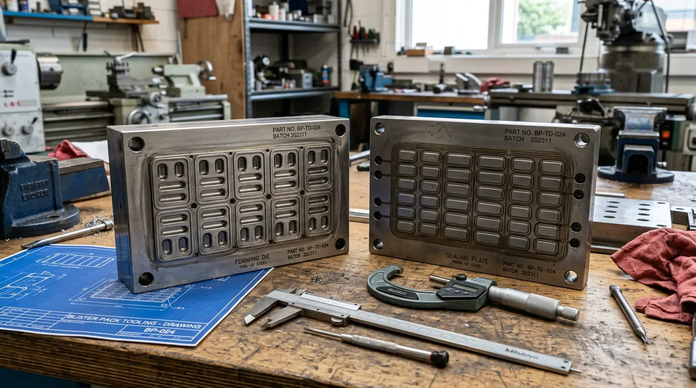
A complete blister line toolset comprises: the forming station tooling (heating plate + forming die), the filling guide (product guidance into cavities), the sealing station tooling (sealing plate + counter tool), and the punching/cutting tools (die cutting the finished blister cards). Each station has its own format-specific tooling that must be changed and re-validated when switching between product formats.
Forming Station Tooling
Thermoform Forming Dies (PVC/PVDC)
Aluminium or brass forming plates with cavity geometry machined to ±0.05 mm tolerance. Heated to 100–140°C for PVC forming. Cavity design incorporates draft angles (1–2°), radii (min. 0.5 mm), and vacuum channels (0.3–0.5 mm dia.) for clean film draw. Multi-cavity layouts balance cavity count with film web width and machine index length.
Cold-Form Tooling (Alu-Alu CFF)
CFF tooling uses mechanical pressure rather than heat to form OPA/foil/PVC or OPA/foil/PE into cavities at room temperature. Forming punch and die must be matched to ±0.02 mm to prevent foil pinholing. Forming depth is typically limited to 6–12 mm (vs. 20+ mm for thermoform) due to foil springback. High-chromium steel with mirror-finish is standard for CFF punch faces.
Sealing Plate Design
The sealing plate applies heat and pressure to bond the foil lidding to the blister web. Key design considerations:
| Parameter | Thermoform (PVC) Lines | CFF (Alu-Alu) Lines |
|---|---|---|
| Plate material | Hard-anodised aluminium | Hardened tool steel |
| Seal temp range | 160–220°C | 200–260°C |
| Pressure | 2–4 bar | 3–6 bar |
| Dwell time | 0.5–1.5 s | 0.8–2.0 s |
| Surface pattern | Crosshatch or smooth | Fine crosshatch (foil adhesion) |
Punching & Cutting Tools
Blister card size and shape are defined by the punching toolset: upper cutting punch (steel, hardened to 60+ HRC) and lower counter-die (steel or polymer). Cutting clearance between punch and die is typically 0.02–0.05 mm — too tight causes burrs; too loose causes incomplete cuts. Punch sharpness is critical and tools require regrinding after 500K–2M cycles depending on film stack gauge and web speed.
Frequently Asked Questions
How many format sets does a typical blister line have?
A production blister line typically carries 3–8 active format sets covering different product SKUs. Each format set includes forming tooling, sealing plate, filling guides, and punching tools specific to that cavity geometry and card size. Format library management — including tooling storage, condition tracking, and SMED-based changeover procedures — is critical for OEE on multi-SKU lines.
What tolerances are required for blister cavity dimensions?
Cavity dimensions must accommodate the product with 0.2–0.5 mm clearance per side for tablets/capsules, allowing reliable filling without jamming while minimising excess headspace. Cavity depth should be 0.5–1.0 mm deeper than maximum product height to ensure the lidding foil can form a flat seal above the product. Tolerances on cavity-to-cavity pitch must be ±0.1 mm to maintain alignment through the sealing station.
How do you validate a new blister toolset?
Toolset validation follows the same IQ/OQ/PQ structure as other packaging equipment. Critical outputs are: cavity fill accuracy (by weight), seal integrity (dye penetration or vacuum decay), blister card dimensional conformance (length, width, perforation position), and push-out force within specification. At least 3 separate production batches at min/nom/max process parameters are typically required for full PQ sign-off.